

TVS tubes and varistors, as efficient circuit protection devices, are widely used in various electronic devices to absorb surges, suppress transient overvoltages, and protect subsequent circuits from damage. The clamping voltage, as one of the core parameters of TVS tubes and varistors, directly affects their protective performance.
Definition of clamping voltage
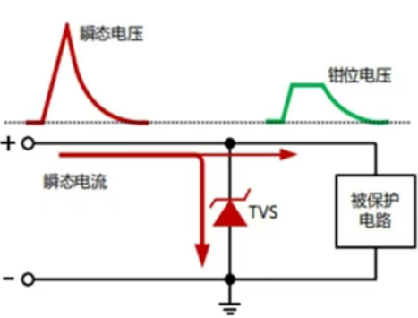
Clamping voltage refers to the peak voltage value at which transient protection devices (such as TVS diodes and varistors) limit the circuit voltage within a safe range when encountering overvoltage. For example, TVS diodes achieve fast voltage limiting through avalanche breakdown mechanism, while varistors rely on nonlinear resistance characteristics to absorb energy and limit voltage
Test conditions for clamping voltage
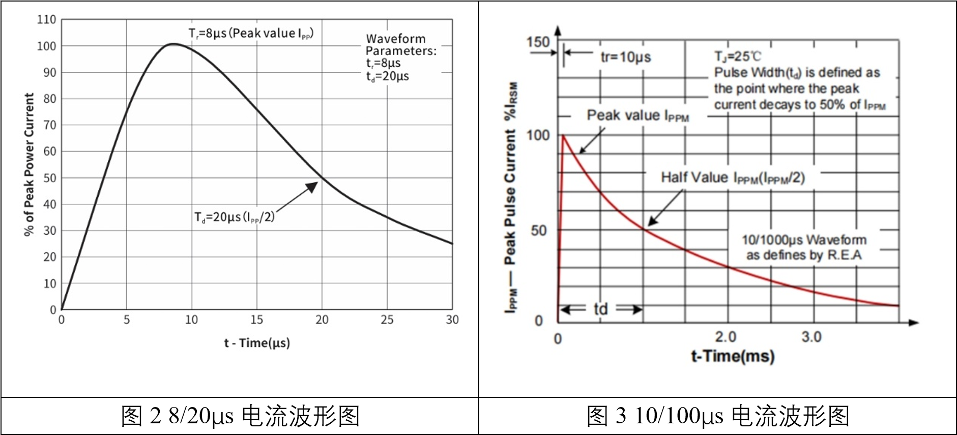
In the data manual of typical TVS tubes and varistors, the test conditions for clamping voltage are 8/20 μ s or 10/1000 μ s current waves. In terms of application standards, the 8/20 μ s test meets the surge immunity requirements of IEC 61000-4-5 for communication equipment and consumer electronics, and the 10/1000 μ s test meets the energy absorption standard of UL 1449 for power port protection devices.
Engineering principles
1,8/20 μ s waveform test:
Simulate short-term high-energy pulses (such as switch surges or induced lightning strikes). The response speed of TVS diode under this waveform can reach nanoseconds, and the dynamic resistance is as low as below 1 Ω, theoretically maintaining the stability of clamping voltage.
The lower the dynamic resistance, the smoother the slope of the clamping voltage rising with the current, and the more stable the protection effect; Varistors need to pay attention to the impact of positive and negative waveform deviations on energy accumulation.
2,10/1000 μ s waveform test:
Simulate long pulse energy shocks (such as direct lightning strikes). The energy tolerance of varistors is calculated using the formula W=1.4 × I × Vc × T. TVS diodes are limited by peak power and need to avoid overheating failure caused by prolonged overcurrent.
Introduction to the Capability of Clamp Voltage Testing in GRGTEST
The equipment used in broadcasting and GRGTEST has the following advantages that can meet the needs of different application scenarios:
1. Current range: 0.5A~350A, suitable for full scene testing from low-power signal lines to high-energy power lines.
2. Current waveform: Supports two standard waveforms: 8/20 μ s (simulating lightning strikes) and 10/1000 μ s (simulating long-period surges)
3. Voltage range: 0~750V, covering the needs of consumer electronics, industrial equipment, and new energy fields.
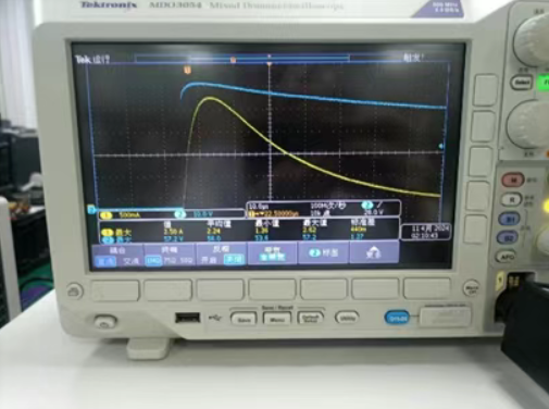
4. High precision and repeatability: The equipment adopts digital control and real-time sampling technology to ensure that the clamping voltage measurement error is less than ± 2%, and supports multi pulse continuous testing to verify the anti fatigue characteristics of the device.

Advantages of GRGTEST Semiconductor Testing Services
● One of the most comprehensive and well-known third-party testing institutions in the field of integrated circuits and SiC technology
● GRGTEST has completed chip validation for hundreds of models including MCU, AI chips, and security chips, and supports the engineering and mass production of multiple models of chips.
● GRGTEST has full service capabilities for AEC-Q and AQG324 in the field of automotive regulations, and have been recognized by nearly 50 car manufacturers