What do QP and AV mean in EMI Conducted Emission Testing?
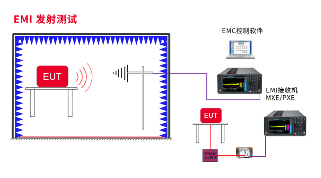
In EMC testing, EMI (Electromagnetic Interference) encompasses Conducted Emissions (CE) testing and Radiated Emissions (RE) testing. CE evaluates interference conducted along power or signal lines, while RE evaluates interference radiated through space as electromagnetic fields. Both assess interference potentially caused to external devices.
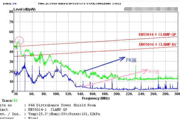
Within EMI conducted emission (CE) testing, what do QP and AVa stand for? The three most commonly referenced measurement types are PK (Peak), QP (Quasi-Peak), and AV (Average).
- PK (Peak): Measures the maximum value occurring within a unit time.
- QP (Quasi-Peak): Measures a weighted average value within a unit time, where the weight depends on both the amplitude and the repetition rate of the pulses.
- AV (Average): Measures the true average value over a unit time.
Detailed Explanation:
1.Peak (PK) Detection:
Features very short charge time constants and long discharge time constants.
Can quickly charge to the stable value of even very narrow pulses and hold the peak voltage for a relatively long time after the signal disappears.
Prioritized in many EMC tests because a single high-amplitude pulse can cause malfunctions (e.g., in digital equipment) without requiring sustained energy over time.
2.Quasi-Peak (QP) Detection:
Features charge and discharge time constants between those of peak and average detectors.
Its output during the measurement period depends on both the amplitude and the repetition rate of the pulses.
Correlates well with the perceived annoyance level of interference to human auditory perception (historically important for broadcast reception).
3.Average (AV) Detection:
Features equal charge and discharge time constants.
Particularly suitable for measuring continuous wave (CW) signals.
Testing Practice:
Testing typically starts by measuring the PK value across the frequency range.
If sufficient margin exists below the limit line for the PK value across all frequencies, testing for QP and AV may be waived (as they will inherently be lower).
Standards like FCC Part 15 and EN 55022 (or its successor EN IEC 55032) specify limits primarily for QP and AV values. The PK limit is often higher or used as a screening tool.
Test receivers usually display the PK trace first. QP and AV values are then derived from this trace using the respective detector modes.
The relationship between the values at any given frequency point is always: PK > QP > AV.