

Simulating the electromagnetic environment in a 10m semi - anechoic chamber is a complex yet crucial task, especially for industries that rely on accurate electromagnetic compatibility (EMC) testing. As a leading supplier of 10m semi - anechoic chambers, I am well - versed in the processes and considerations involved in creating a reliable simulation. In this blog, I will share some key insights on how to simulate the electromagnetic environment in such a chamber.
Understanding the Basics of a 10m Semi - Anechoic Chamber
A 10m semi - anechoic chamber is a specialized testing facility designed to minimize the reflection of electromagnetic waves. It consists of a large room with walls, ceiling, and floor covered with absorbers that absorb most of the incident electromagnetic energy. The "10m" refers to the distance between the test antenna and the device under test (DUT), which is a standard distance for many EMC tests.
The semi - anechoic nature of the chamber means that the floor is usually made of a conductive material, while the walls and ceiling are lined with absorbers. This setup allows for the simulation of real - world electromagnetic scenarios, where the ground plays a significant role in the propagation of electromagnetic waves.
Step 1: Define the Simulation Objectives
Before starting the simulation, it is essential to clearly define the objectives. What kind of electromagnetic environment do you want to simulate? Is it a specific frequency range, a particular type of interference, or a combination of different scenarios? For example, if you are testing a wireless device, you may want to simulate the electromagnetic environment of a crowded urban area with multiple wireless signals.
Step 2: Select the Appropriate Simulation Tools
There are several simulation tools available in the market that can be used to simulate the electromagnetic environment in a 10m semi - anechoic chamber. These tools range from commercial software packages to open - source solutions. Some popular commercial software includes CST Studio Suite, HFSS, and FEKO. These tools offer advanced features for electromagnetic field simulation, such as finite element method (FEM), method of moments (MoM), and transmission line matrix (TLM).
Open - source tools like OpenEMS can also be a viable option, especially for those on a budget or who want to have more control over the simulation process. These tools often require a certain level of technical expertise but can provide accurate results if used correctly.
Step 3: Model the Chamber and the DUT
Once you have selected the simulation tool, the next step is to model the 10m semi - anechoic chamber and the device under test. The chamber model should accurately represent the dimensions, the properties of the absorbers, and the conductive floor. The absorber properties, such as the absorption coefficient and the frequency response, need to be carefully defined based on the actual characteristics of the absorbers used in the chamber.
The device under test should also be modeled in detail. This includes its physical dimensions, the location and orientation of the antennas (if applicable), and the electrical properties of its components. For complex devices, it may be necessary to use simplified models that capture the essential electromagnetic behavior.

Step 4: Define the Source of Electromagnetic Waves
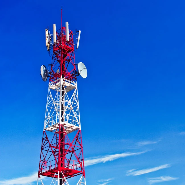
To simulate the electromagnetic environment, you need to define the source of the electromagnetic waves. This can be a single antenna, multiple antennas, or a combination of different sources. The characteristics of the source, such as the frequency, power, polarization, and radiation pattern, need to be specified.
For example, if you are simulating a wireless communication scenario, you may need to define multiple antennas representing different base stations or other wireless devices. The radiation patterns of these antennas can be obtained from the manufacturer's specifications or measured in a laboratory.
Step 5: Set Up the Simulation Parameters
After defining the chamber, the DUT, and the source, you need to set up the simulation parameters. This includes the frequency range, the time step (for time - domain simulations), the mesh size, and the boundary conditions. The frequency range should cover the frequencies of interest for the electromagnetic environment you are simulating.
The mesh size is an important parameter that affects the accuracy and the computational cost of the simulation. A finer mesh generally provides more accurate results but requires more computational resources. The boundary conditions define how the electromagnetic waves interact with the boundaries of the simulation domain.
Step 6: Run the Simulation and Analyze the Results
Once all the parameters are set up, you can run the simulation. The simulation may take some time, depending on the complexity of the model and the computational resources available. After the simulation is complete, you need to analyze the results.
The analysis may include examining the electromagnetic field distribution inside the chamber, the coupling between the source and the DUT, and the performance of the DUT under the simulated electromagnetic environment. You can use the visualization tools provided by the simulation software to view the results in a graphical form.
Step 7: Validate the Simulation Results
To ensure the accuracy of the simulation results, it is necessary to validate them against experimental measurements. This can be done by conducting actual EMC tests in the 10m semi - anechoic chamber using the same setup as in the simulation. Compare the simulation results with the experimental data, and if there are significant differences, adjust the simulation model and parameters accordingly.
Applications of Electromagnetic Environment Simulation in a 10m Semi - Anechoic Chamber
The simulation of the electromagnetic environment in a 10m semi - anechoic chamber has many applications. One of the most common applications is in the field of EMC testing. EMC tests are used to ensure that electronic devices can operate properly in the presence of electromagnetic interference and do not generate excessive electromagnetic emissions.
For example, Wireless SRRC Certification and Testing requires accurate simulation of the electromagnetic environment to ensure that wireless devices meet the regulatory requirements. The simulation can help in predicting the performance of the device under different electromagnetic scenarios and in identifying potential problems before the actual testing.
Another important application is Radiated Immunity (RS)Test. In this test, the device under test is exposed to a radiated electromagnetic field to evaluate its immunity to such interference. Simulation can be used to optimize the test setup and to predict the response of the device to different levels of electromagnetic radiation.
Electrostatic Discharge ESD Testing is also an area where simulation can be useful. ESD can cause serious damage to electronic devices, and simulation can help in understanding the mechanism of ESD coupling and in designing effective protection measures.
Conclusion
Simulating the electromagnetic environment in a 10m semi - anechoic chamber is a challenging but rewarding task. By following the steps outlined in this blog, you can create accurate simulations that can help in improving the electromagnetic performance of electronic devices and in ensuring compliance with regulatory requirements.
As a supplier of 10m semi - anechoic chambers, we are committed to providing high - quality chambers and supporting our customers in their electromagnetic simulation and testing needs. If you are interested in purchasing a 10m semi - anechoic chamber or need assistance with electromagnetic environment simulation, please feel free to contact us for a detailed discussion and procurement negotiation.
References
- Balanis, C. A. (2016). Antenna Theory: Analysis and Design. Wiley.
- Paul, C. R. (2006). Introduction to Electromagnetic Compatibility. Wiley - Interscience.
- Rao, S. S. (2009). Electromagnetic Field Computation by the Finite Element Method. CRC Press.